Su carrito de compras está vacío
 
English Polski Spanish 
Buscar un manual
 

(p.Ej. AA-V20EG JVC, ZX-7 Sony)
PayPal 1000+ rating Secure, Encrypted Checkout.
 
Usuarios conectados
Actualmente hay 5833 visitantes online.
Productos
Información
Destacado
Inicio >> MINOLTA >> CF2001 Manual de Servicio
 
 0 artículo(s) en Su carrito 

MINOLTA CF2001
Manual de Servicio


¡Twitee acerca de este producto y obtenga $1.00 de crédito en la tienda para uso!
  • Contiene diagramas del circuito
  • Descargable
  • Formato PDF
  • Manual completo
  • Idiomas: English
Precio: $4.99

Descripción del MINOLTA CF2001 Manual de Servicio

Manual de servicio completo en formato digital (archivo PDF). Los manuales de servicio por lo general contienen diagramas de circuitos, tarjetas de circuitos impresos, consejos para reparación, diagramas de cableado, diagramas de bloque y lista de refacciones. El Manual de Servicio (a veces llamado Manual de Reparación) es usado principalmente por los técnicos.

Si tan solo quiere saber cómo utilizar su televisión, reproductor de vídeo, reproductor de mp3, etc. Quizá lo que necesita es el Manual del Propietario. Después de colocar la orden le enviaremos las instrucciones de descarga a su dirección de e-mail.

The manual is available in languages:

Not yet ready
You must purchase it first

Opiniones de los clientes
No hay comentarios de productos.

TEXT_PDF_SNIPPET
4.
4-1.

OTHER ADJUSTMENTS
Adjustment of the Position of the Scanner and 2nd/3rd Mirrors Carriage

Requirement � With the Scanner Assy fixed to the Scanner Drive Cables, there should be no gap between the Scanner/Mirrors Carriage Positioning Jig and the Scanner and also between the Scanner/Mirrors Carriage Positioning Jig and the 2nd/3rd Mirror Carriage. This adjustment must be made in any of the following cases: � The Scanner Drive Cable has been replaced. � The Scanner Fixing Bracket has been removed from the Scanner Drive Cable. � The Scanner Drive Cable comes unwound. Adjustment Procedure 1. Remove the IR Rear Upper Cover, IR Front Cover, IR Right Cover, and Original Glass. 2. Move the Scanner Assy so that the Scanner Positioning Screw is aligned with the hole in the upper frame. 3. Insert a screwdriver into the hole in the upper frame and loosen the Scanner Positioning Screw.
4004D218AA

NOTE � Do not remove the Scanner Positioning Screw.

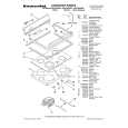
Scanner positioning Screws

4004D203AA

4. Install the Scanner Positioning Jigs between the Scanner Assy and the 2nd/3rd Mirrors Carriage Assy.

4004D219AA

D-90

Quizás también quiera comprar

$4.99

CF2001 MINOLTA
Manual de Usuario

Manual del propietario completo en formato digital. El manual estará disponible para descarga como …
>
Parse Time: 0.183 - Number of Queries: 103 - Query Time: 0.045